Field Clearances
- General Overview
- Related Tools
Beam connections: non-auto standard
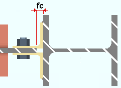
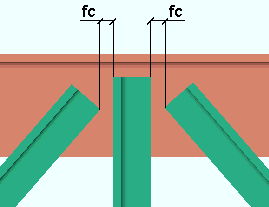
Shear plates: The distance between the end of the beam to the face of the supporting member or, for an extend-past-flange beam-to-beam shear plate, the distance between the beams. This field clearance applies to shear plates whose specifications are entered on the Beam Edit window and to user defined shear plates. Connection design calculates the distance from the face of the support to the column of holes in the shear plate using the field clearance entered here plus the beam's end edge distance. This is then rounded up to the next 1/4 inch (or even millimeters for metric). As a result, the actual calculated field clearance may be larger than specified, but not less.
|
fc = field clearance |
Shear tees: The distance from the face of the connection to the face of the supporting member. This applies to shear tees that field bolt to the supporting member (beam or column) and Attach in the shop to the supported member (the beam). This field clearance applies to shear tees whose specifications are entered on the Beam Edit window and to user defined shear tees.
|
fc = field clearance |
Clip angle on supported: The distance from the face of the connection to the face of the supporting member. This applies to clip angles that field bolt to the supporting member (beam or column) and attach in the shop to the supported member (the beam). This field clearance applies to shop-attached-to-supported clip angles whose specifications are entered on the Beam Edit window and to user defined clip angles.
|
fc = field clearance |
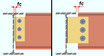
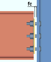
Clip angle on supporting: The distance from the face of the supporting member to the web of the beam that the clip angles field bolt to. This applies to clip angles that shop weld to the supporting member (beam or column) and field bolt to the supported member (the beam). This field clearance applies to shop-attached-to-supporting clip angles whose specifications are entered on the Beam Edit window and to user defined clip angles.
|
fc = field clearance |
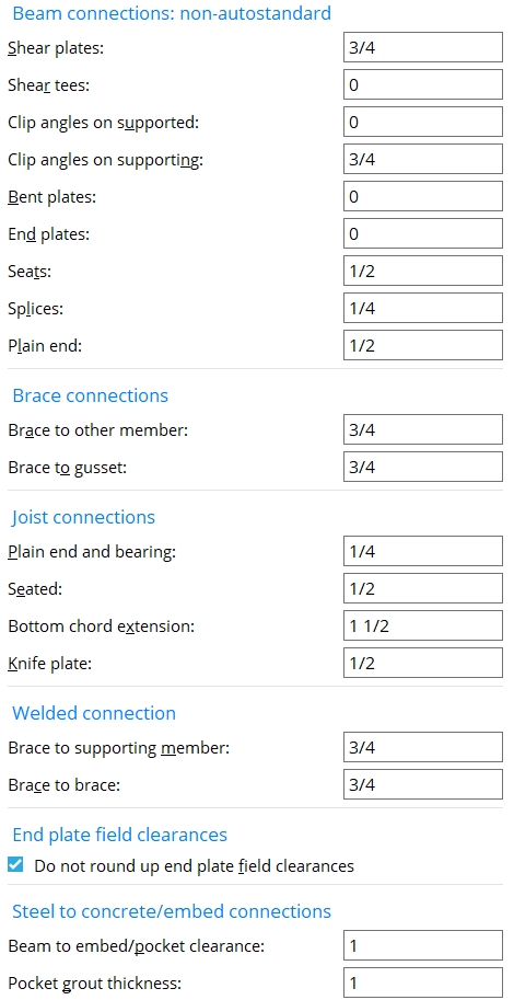
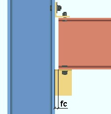
Bent plates: The distance from the face of the connection to the face of the supporting member. This applies to bent plates that field bolt to the supporting member (beam or column) and attach in the shop to the supported member (the beam). This field clearance applies to bent plates whose specifications are entered on the Beam Edit window and to user defined bent plates.
|
|
fc = field clearance |
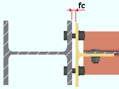
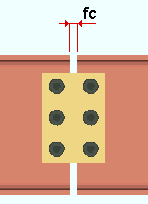
End plates: The distance from the face of the connection to the face of the column. This field clearance applies to end plates whose specifications are entered on the Beam Edit window and to user defined end plates.
|
fc = field clearance |
Also see: Do not round up end plate field clearances (on this page)
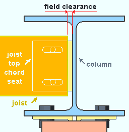
Seats: The distance from the end of the beam to the face of the column. This field clearance applies to beam seats whose specifications are entered on the Beam Edit window and to user defined beam seats.
|
fc = field clearance |
Splices: The distance between the two beams. This field clearance applies to beam splices whose specifications are entered on the Beam Edit window and to user defined beam seats.
|
fc = field clearance |
Plain end: The distance between the beam and the beam or column that the beam frames to. This applies when the beam's Input connection type is Plain end.
|
fc = field clearance |
Brace connections
Brace to other member: The distance between the end of the brace and the face of the supporting beam or column. Or it is the distance between the end fitting on the brace and the face of the supporting beam or column. Or it is the distance between the end of the brace and the clip angle that bolts the gusset to the supporting member.
For the field clearance between a brace and a sloping beam or sloping column, the distance is measured perpendicular from the beam to the brace. This applies when the
|
fc = field clearance |
Brace to gusset: The distance between the end of the brace and the edge of the gusset plate. This applies to any pipe or tube horizontal brace or when the Pipe/tube end-fitting on an pipe or tube vertical brace is a Paddle plate (as illustrated below) or Bolted.
|
fc = field clearance |
Joist connections
Plain end and bearing: The distance parallel with the workline of the joist from the input point of the joist (X) to the top of the joist's top chord. This distance is measured along the top of the top chord of the joist. This clearance may be applied when the joist Input connection type is Plain end or Bearing or User defined or Auto Standard.
|
joist to beam |
Note 1: The clearance affects the Overall Length reported in the Joist Report as well as positions the joist on the beam's top flange.
Note 2: The value entered here can impact the connection failure message Beam flange too narrow for min joist bearing.
Seated: The distance parallel with the workline of the joist from the top edge of the joist's top chord to the face of the supporting member.
|
seated joist |
Bottom chord extension: The distance from the edge of the joist's extended bottom chord to the face of the supporting member. This clearance may be applied when the joist Input connection type is Flush framed shear or Bearing or Seated or User defined or Auto standard. The joist can frame to a beam or column. Bearing connections can be applied to a column with a cap plate as well as to the top flange a beam. Flush framed shear connections can be applied to a beam or column. Seated connections can be applied to a column.
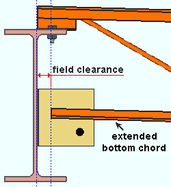
|
A joist with a bearing connection and an extended bottom chord. |
Knife plate: The distance from the edge of the joist's knife plate to the face of the supporting member (beam or column). This clearance may be applied when the joist Input connection type is Flush framed shear or Flush framed clip angle or User defined or Auto standard. A flush framed shear connection can be designed as the end connection for a joist to a beam or column.
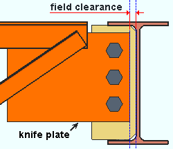
|
A joist with a Flush framed shear connection that frames to a beam. |
Welded connections
| These options apply when the Input connection type on a vertical brace is Welded and the vertical brace is a Back to back double-angle to the stem of a W tee (or S tee) chord member. Typically a W tee beam is used as the chord member. |
Brace to supporting member: The distance from the end of the back-to-back double-angle vertical brace to the k distance of the W tee or S tee. This applies to 1-point, 2-point and 3-point vertical bracing.
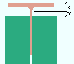 fc = field clearance
Brace to brace: The distance between any two adjacent back-to-back double-angle braces in a 2-point or 3-point branch. Connection design calculates the field clearance between the vertical braces assuming that the two or three double-angle braces share the same work point. If the work points are some distance apart from one another, the actual field clearance may be something other than the distance that is entered here.
 fc = field clearance
End plate field clearances
Do not round up end plate field clearances: ![]() or
or ![]() . This option applies to field clearances on all system designed end plates, auto standard and non-auto standard.
. This option applies to field clearances on all system designed end plates, auto standard and non-auto standard.
If this box is checked (
), connection design will generate all end plate connections without using the rounding procedure that could result in a 1/16-inch (or 1-mm) extra gap being added to an end plate's field clearance. As a result, an end plate's field clearance will more likely be as specified for End plates on this screen, or in Project Settings > Job > Connections > Auto Standard Connections.
If the box is not checked (
), connection design may continue to add a 1/16-inch (or 1-mm) extra gap to the user-specified field clearance for particular situations. The additional gap will most likely be added if your beams are sloping or if your primary dimension Units are set to Metric.
Steel to concrete/embed connections
Beam to embed/pocket clearance: The distance from the end of the beam to the face of the embed or the pocket. This affects the Automatic minus dimension that is applied to a beam with a shear plate or clip angle to an embed plate, or a beam with a bearing connection. Entering an Input minus dimension overrides this end clearance for individual beams.
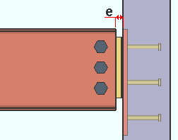
|
e = end clearance |
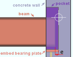
|
e = pocket clearance |
Beam-to-concrete bearing connections: A bearing plate or angle or channel embed can be created in the model from the Beam Edit window by selecting Bearing as the Input connection type and making an Embed schedule entry.
Joist-to-concrete bearing connections: A joist end pocket is created in a concrete wall or tilt-up panel when Bearing is selected as the Input connection type on the Joist Edit window and the joist top chord frames to the concrete wall or panel.
Pocket grout thickness: The distance from the bottom of the beam to the bottom of the pocket. For a joist, this distance is from the bottom of the joist's shoe to the bottom of the pocket.
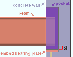
|
The grout bearing thickness (g) positions the bottom of the pocket and also positions the embed (a bearing plate in this example). A bearing embed can also be an angle or a channel. |
Beam steel-to-concrete connections: A bearing plate or angle or channel embed can be created in the model from the Beam Edit window by selecting Bearing as the Input connection type and making an Embed schedule entry. For a beam, this field clearance sets the value that is entered to Grout thickness when that option is unlocked
( in the)
leaf. Beam End Pocket
Joist steel-to-concrete connections: A joist end pocket is created in a concrete wall or tilt-up panel when Bearing is selected as the Input connection type on the Joist Edit window and the joist top chord frames to the wall or panel. For a joist, this clearance sets the Grout thickness when that option is unlocked
( in theleaf.


|
|
OK (or the Enter key) closes this screen and applies the settings.
Cancel (or the Esc key) closes this screen without saving any changes.
Reset undoes all changes made to this screen since you first opened it. The screen remains open.
- User defined connections (set up using this screen)
- Beam Edit connections (set up using this screen)
- Auto Standard Field Clearance (additional field clearance options)

